Node.js 樹莓派 GPIO - 流動LED
使用陣列和輸出建立流動LED
在本章中,我們將使用多個GPIO引腳,透過按順序開啟和關閉它們來建立“流動”效果。
What do we need?
For this you need
- A Raspberry Pi with Raspian, internet, SSH, with Node.js installed
- Node.js 的 onoff 模組
- 1 x Breadboard
- 8個220歐姆電阻
- 8個直插式LED
- 9根母對公跳線
注意:您需要的電阻可能與我們使用的不同,具體取決於您使用的LED型別。大多數小型LED只需要一個小的電阻,大約200-500歐姆。通常,您使用的確切值並不重要,但電阻值越小,LED就會越亮。
Click the links in the list above for descriptions of the different components.
Building the Circuit
Now it is time to build the circuit on our Breadboard.
If you are new to electronics, we recommend you turn off the power for the Raspberry Pi. And use an anti-static mat or a grounding strap to avoid damaging it.
Shut down the Raspberry Pi properly with the command
pi@w3demopi:~ $ sudo shutdown -h now
After the LEDs stop blinking on the Raspberry Pi, then pull out the power plug from the Raspberry Pi (or turn of the power strip it is connected to).
Just pulling the plug without shutting down properly may cause corruption of the memory card.
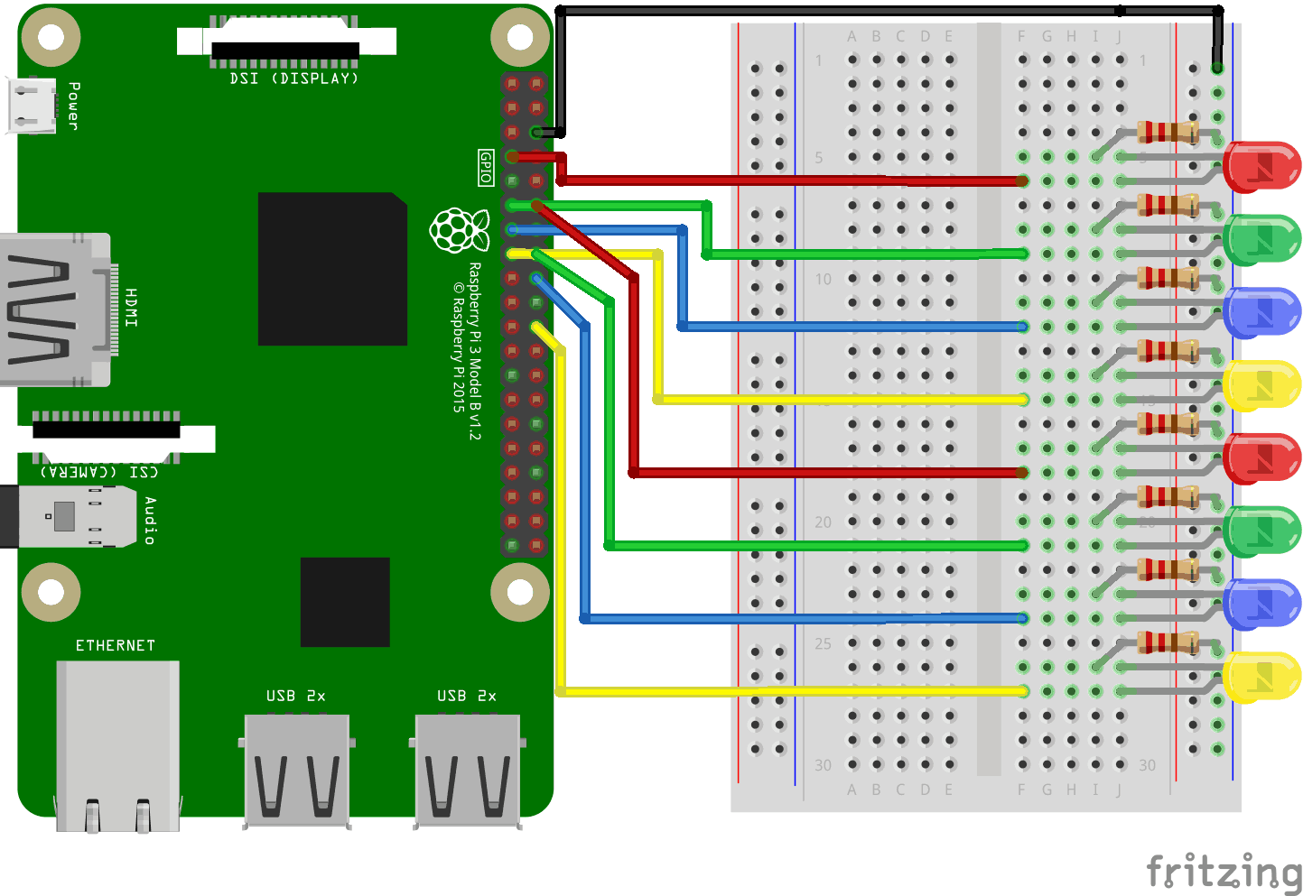
Look at the above illustration of the circuit.
- 在樹莓派上,將跳線母頭連線到GND引腳。在我們的示例中,我們使用了物理引腳6(GND,第3行,右列)
- 在麵包板上,將連線到GND電源的跳線公頭連線到右側的接地匯流排。麵包板的整個列都連線在一起,所以連線到哪一行並不重要。在我們的示例中,我們將其連線到第1行
- 對於每個LED:連線LED,使其連線到2個連線點行。在我們的示例中,我們連線了
- LED1連線到第5行(陰極)和第6行(陽極)J列
- LED2連線到第8行(陰極)和第9行(陽極)J列
- LED3連線到第11行(陰極)和第12行(陽極)J列
- LED4連線到第14行(陰極)和第15行(陽極)J列
- LED5連線到第17行(陰極)和第18行(陽極)J列
- LED6連線到第20行(陰極)和第21行(陽極)J列
- LED7連線到第23行(陰極)和第24行(陽極)J列
- LED8連線到第26行(陰極)和第27行(陽極)J列
- 對於每個LED:將220歐姆電阻的一條腿連線到右側的接地匯流排列,另一條腿連線到與LED陰極腿相連的右側連線點行。在我們的示例中,我們連線了
- LED1連線到第5行I列
- LED2連線到第8行I列
- LED3連線到第11行I列
- LED4連線到第14行I列
- LED5連線到第17行I列
- LED6連線到第20行I列
- LED7連線到第23行I列
- LED8連線到第26行I列
- 對於每個LED:將跳線母頭連線到樹莓派上的GPIO引腳,並將跳線公頭連線到與LED陽極腿相連的右側連線點行。在我們的示例中,我們連線了
- LED1從物理引腳7(GPIO 4,第4行,左列)連線到連線點第6行F列
- LED2從物理引腳11(GPIO 17,第6行,左列)連線到連線點第9行F列
- LED3從物理引腳13(GPIO 27,第7行,左列)連線到連線點第12行F列
- LED4從物理引腳15(GPIO 22,第8行,左列)連線到連線點第15行F列
- LED5從物理引腳12(GPIO 18,第6行,右列)連線到連線點第18行F列
- LED6從物理引腳16(GPIO 23,第8行,右列)連線到連線點第21行F列
- LED7從物理引腳18(GPIO 24,第9行,右列)連線到連線點第24行F列
- LED8從物理引腳22(GPIO 25,第11行,右列)連線到連線點第27行F列
Your circuit should now be complete, and your connections should look pretty similar to the illustration above.
Now it is time to boot up the Raspberry Pi, and write the Node.js script to interact with it.
樹莓派和Node.js流動LED指令碼
進入“nodetest”目錄,建立一個名為“flowingleds.js”的新檔案
pi@w3demopi:~ $ nano flowingleds.js
The file is now open and can be edited with the built in Nano Editor.
Write, or paste the following
flowingleds.js
var Gpio = require('onoff').Gpio; //包含onoff以與GPIO互動
var LED04 = new Gpio(4, 'out'), //為所有GPIO輸出引腳宣告變數
LED17 = new Gpio(17, 'out'),
LED27 = new Gpio(27, 'out'),
LED22 = new Gpio(22, 'out'),
LED18 = new Gpio(18, 'out'),
LED23 = new Gpio(23, 'out'),
LED24 = new Gpio(24, 'out'),
LED25 = new Gpio(25, 'out');
//將所有LED變數放入一個數組中
var leds = [LED04, LED17, LED27, LED22, LED18, LED23, LED24, LED25];
var indexCount = 0; //一個計數器
dir = "up"; //流動方向變數
var flowInterval = setInterval(flowingLeds, 100); //每100毫秒執行flowingLeds函式
function flowingLeds() { //流動LED函式
leds.forEach(function(currentValue) { //對於陣列中的每個專案
currentValue.writeSync(0); //關閉LED
});
if (indexCount == 0) dir = "up"; //如果計數達到零,則將流動方向設定為“up”
if (indexCount >= leds.length) dir = "down"; //如果計數達到7,則將流動方向設定為“down”
if (dir == "down") indexCount--; //如果方向向下,則向下計數
leds[indexCount].writeSync(1); //開啟陣列索引與計數匹配的LED
if (dir == "up") indexCount++ //如果方向向上,則向上計數
};
function unexportOnClose() { //退出程式時執行的函式
clearInterval(flowInterval); //停止流動間隔
leds.forEach(function(currentValue) { //對於每個LED
currentValue.writeSync(0); //關閉LED
currentValue.unexport(); //取消匯出GPIO
});
};
process.on('SIGINT', unexportOnClose); //使用者使用ctrl+c關閉時執行的函式
Press "Ctrl+x" to save the code. Confirm with "y", and confirm the name with "Enter".
Run the code
pi@w3demopi:~ $ node flowingleds.js
現在LED應該按順序開啟和關閉,形成流動效果。
End the program with Ctrl+c.